Potentiostats for Battery Research Testing

Potentiostats for Battery Research Testing

Take two different metals, place an ion transporting medium between them, wire them up to be connected outside the electrolyte solution (perhaps to a voltmeter or potentiostat) and you’ve made a battery. With the ever-increasing demand for portable power, batteries are becoming more and more important. As demands on battery performance increase, so do demands Read more about Potentiostats for Battery Research Testing[…]

The Working electrode is not at Virtual Ground

Potentiostat Architectures – Passive I/E Converters

A Common Potentiostat Design

This style of I/E Converter is well suited to potentiostats with output currents of a few tenths of an ampere up to several A Common Potentiostat Design
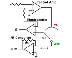
amperes. This scheme has been used by Gamry, PAR, Solartron, and perhaps others.

The I/E Converter is a “passive” design

The current path through the I/E converter only traverses passive components such as wires and resistors. No active components (such as op amps or transistors) are in the current path. The current measurement resistor is connected between the Working electrode and the potentiostat’s power supply ground (or “current return”).

The Working electrode is not at Virtual Ground

This is a consequence of the passive design. The working electrode voltage (vs the potentiostat’s internal ground) depends on the current flowing. In the sketch shown to the right, the working electrode will be at (i*Rm) volts. The actual voltage may be higher due to the resistance of the cell cable connecting the potentiostat to the working electrode!

Potentiostat with differential electrometer

[…]

Even if the I/E circuit is not overloaded, it can have severe influence on potentiostat stability.

Potentiostat Architectures – Active I/E Converters

The Classical Potentiostat The schematic at the right is the classical potentiostat design shown in nearly every modern electrochemistry textbook. It has three basic features. The Working electrode is at Virtual Ground. The working electrode is at the same potential as the potentiostat’s electronic ground. This ground is often connected to Earth Ground. The electrometer Read more about Potentiostat Architectures – Active I/E Converters[…]

Electrochemical Quantitative Corrosion Theory

Quantitative Corrosion Theory

In the previous post (Electrochemical Corrosion Measurements Primer) we pointed out that Icorr cannot be measured directly. In many cases, you can estimate it from current versus voltage data. You can measure a log current versus potential curve over a range of about one half volt. The voltage scan is centered on Eoc. You then fit the measured data to a theoretical model of the corrosion process.

The model we will use for the corrosion process assumes that the rates of both the anodic and cathodic processes are controlled by the kinetics of the electron transfer reaction at the metal surface. This is generally the case for corrosion reactions. An electrochemical reaction under kinetic control obeys Equation 1-1, the Tafel Equation.

the Tafel Equation

Equation 1-1

[…]

Electrochemical Quartz Crystal Microbalance - Gamry Instruments's eQcm

Quartz Crystal Microbalance

The Quartz Crystal Microbalance (QCM) is an exciting tool for the electrochemist. With it, the researcher can now follow not only the current that flows, but the weight changes of the electrode, too! This is a valuable tool when studying reactions which involve films, adsorbates, metal deposition, corrosion, or monolayer formation. It is sensitive enough Read more about Quartz Crystal Microbalance[…]

Reference Electrodes

Introduction

This Application Note presumes that you have a basic understanding of potentiostat operation. If you are not that knowledgeable concerning electrochemical instrumentation, please read Potentiostat Fundamentals before continuing. Experienced potentiostat users may skip the primer and read on.

It’s only natural that electrochemists concentrate on the working electrode. After all, reactions at the working electrode are Silver Chloride Reference Electrodewhat they study. However, the reference electrode shouldn’t be ignored. Its characteristics can greatly influence electrochemical measurements. In some cases, an apparently “good” reference electrode can cause a complete failure of the system.

For reliable reference electrode performance, you should assign a “Lab Master” and treat it very, very carefully so it can serve as a standard for your other reference electrodes. Never use the Lab Master in an actual experiment. The only purpose of the Lab Master is to serve as a check for the other reference electrodes. If a reference electrode is suspected to be bad, you can check the potential versus the Lab Master. You can do that with a voltmeter, or with your Gamry Potentiostat by running and open circuit potential. If the potential difference is less than 2-3 mV, it’s OK. If it’s higher than 5 mV, it needs to be refreshed or discarded.

[…]

Gamry Interface - Reference Potentiostats

Potentiostat Fundamentals

Introduction

A potentiostat is an electronic instrument that controls the voltage difference between a Working Electrode and a Reference Electrode. Both electrodes are contained in an electrochemical cell. The potentiostat implements this control by injecting current into the cell through an Auxiliary or Counter electrode.

In almost all applications, the potentiostat measures the current flow between the Working and Counter electrodes. The controlled variable in a potentiostat is the cell potential and the measured variable is the cell current.

Gamry Potentiostat

Prerequisites

This Application Note may be difficult to follow unless you have some familiarity with electrical terms such as voltage, current, resistance, frequency, and capacitance. If you feel your knowledge in this area is lacking, we suggest review of a very basic electronics or physics book.

Electrodes

A potentiostat requires an electrochemical cell with three electrodes as shown below. W/WS denote the working and working sense. R denotes the reference electrode and C denotes the counter electrode.

Potentiosta: Electrochemical cell-3 electrodes […]

measuring surface related currents

Measuring Surface Related Currents

Using Digital Staircase Voltammetry

Introduction

Cyclic Voltammetry (CV) is unarguably the most popular electrochemical technique. It owes its well deserved reputation to its ability to deduce reaction mechanisms with relatively low cost equipment and quick experimentation. Since the very highly cited paper by Nicholson and Shain1 the technique has been the centerpiece of any electrochemical study.

CV involves sweeping the potential linearly between two limits at a given sweep rate while measuring current. The sweep rate chosen can be varied from few microvolts per second to millions of volts per second.

Electrochemical instrumentation has evolved vastly since the days of Nicholson and Shain. Currently, most manufacturers (including Gamry) make digital instruments with digital signal generators. These signal generators approximate the linear sweep with a staircase of variable step sizes and durations.

CV Electrochemical Technique

Figure 1 Staircase vs analog ramp

[…]

This website uses cookies to ensure you get the best experience on our website. More information

The cookie settings on this website are set to "allow cookies" to give you the best browsing experience possible. If you continue to use this website without changing your cookie settings or you click "Accept" below then you are consenting to this. Please review our Privacy Policy

Close