The Classical Potentiostat
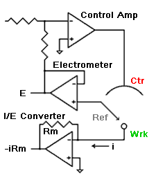
The schematic at the right is the classical potentiostat design shown in nearly every modern electrochemistry textbook. It has  three basic features.
The Working electrode is at Virtual Ground.
The working electrode is at the same potential as the potentiostat’s electronic ground. This ground is often connected to Earth Ground.
The electrometer is single ended.
The circuitry measures the potential of the reference electrode with respect to the electronic “ground”, or zero volt reference point.
Schematic of a Potentiostat with Current Follower I/E
The “3 Op-Amp” Potentiostat The PAR M173 used this architecture.
The I/E Converter is a “current follower” design.
I prefer to call this an “active” I/E converter since the I/E Converter amplifier does double duty. It converts the current, i, into voltage (-i*Rm), but it is also responsible for maintaining the Working electrode at virtual ground.
Advantages
Both the measured current signal and the measured voltage signal are referenced to the potentiostat’s ground. This makes for easy interconnection to an oscilloscope or data acquisition system without the need for differential amplifiers.
The Working electrode is easily protected from noise by using coax cable and grounding the shield.
Disadvantages
Whenever the current measurement circuit is overloaded theworking electrode is no longer maintained at virtual ground. The net result is loss of potential control.
Even if the I/E circuit is not overloaded, it can have severe influence on potentiostat stability. The I/E converter must be de-tuned in order to insure potentiostat stability.
This design is not well suited for high current potentiostats since two high current amplifiers must be designed and built; one for the Control Amplifier and one for the I/E Converter.
