
This tutorial provides an introduction to the quartz crystal microbalance (QCM), which is an instrument that allows a user to monitor small mass changes on an electrode. The reader is directed to the numerous reviews1 and book chapters2 for a more in-depth description concerning the theory and application of the QCM. A basic understanding of electrical components and concepts is assumed.
The two major points of this document are:
Explanation of the Piezoelectric Effect
Equivalent Circuit Models
The Piezoelectric Effect
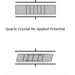
Figure 1. Graphical Representation of Thickness Shear Deformation.
The application of a mechanical strain to certain types of materials (mostly crystals) results in the generation of an electrical potential across that material. Conversely, the application of a potential to the same material results in a mechanical strain (a deformation). Removal of the potential allows the crystal to restore to its original orientation. The igniters on gas grills are a good example of everyday use of the piezoelectric effect. Depressing the button causes the spring-loaded hammer to strike a quartz crystal thereby producing a large potential that discharges across a gap to a metal wire igniting the gas.
Quartz is by far the most widely utilized material for the development of instruments containing oscillators partly due to historical reasons (the first crystals were harvested naturally) and partly due to its commercial availability (synthetically grown nowadays). There are many ways to cut quartz crystals and each cut has a different vibrational mode upon application of a potential. The AT-cut has gained the most use in QCM applications due to its low temperature coefficient at room temperature. This means that small changes in temperature only result in small changes in frequency. It has a vibrational mode of thickness shear deformation as shown below in Figure 1.
The application of an alternating potential (a sine wave in nearly all cases) to the crystal faces causes the crystal to oscillate. When the thickness of the crystal (tq) is twice the acoustical wavelength, a standing wave can be established where the inverse of the frequency of the applied potential is of the period of the standing wave. This frequency is called the resonant frequency, f0, and is given by the equation
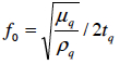
where μq is the shear modulus (a ratio of sheer stress to shear strain), ρq is the density, and tq is the crystal thickness. The amount of energy lost during oscillation at this frequency is at a minimum. The ratio of peak energy stored to energy lost per cycle is referred to as the quality factor, Q, and is given by the equation

where fc is the center frequency and fFWHM is the full width at half max. This full width at half max is also called the bandwidth. For quartz crystals in air, Q can exceed 100,000 while in solution Q decreases to ~3000. This is because the crystal has been damped by the solution. This damping increases the amount of energy lost per cycle, decreasing Q as shown in Figure 2 below.
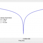
Figure 2. Comparison of High Q (solid line) and Low Q (dashed line).
Continue reading the Application Note Basics of QCM and Equivalent Circuit Model. You will also have an opportunity to download this note in PDF format.