Penn State Annual Corrosion Short Course

Gamry Instruments to Co-Sponsor the 24th Annual Penn State University Corrosion Short Course

Registration is open for The Penn State University’s 24th Annual Corrosion Short Course scheduled for June 7-12, 2020 at the University Park Campus in State College, PA (USA). Gamry Instruments will be a co-sponsor for the course. Philadelphia, PA, January 27, 2020 – Registration is now open for the annual Penn State University Corrosion Short Read more about Gamry Instruments to Co-Sponsor the 24th Annual Penn State University Corrosion Short Course[…]

Visit Gamry Instruments' newly launched website

Gamry Instruments Launches New Website

Warminster, Pa — Gamry Instruments, a leader in electrochemical impedance spectroscopy instrumentation, is proud to announce the launch of a new website designed to help researchers and academia find the right instrumentation for every application. The new website features a potentiostat selection tool, a first in the industry.  This groundbreaking interface allows visitors to enter Read more about Gamry Instruments Launches New Website[…]

cyclic voltammetry scan rate

How Fast a CV Can I Measure Reliably ?

Being able to scan rapidly does not insure that the results will be meaningful! The speed of the current measurement circuitry is often the limiting factor!

The key to finding the practical limit for obtaining meaningful fast scan cyclic voltammograms is nearly always finding the speed of the current measurement. Here the researcher has an important role to play: It is the researcher who must select the current range to use for fast cyclic voltammetry. The autoranging capability of many modern computer controlled potentiostats generally cannot be used because the decisions cannot be made and implemented fast enough.

Because of stray (and deliberately added) capacitances, the current measuring circuitry generally becomes slower as the full scale current decreases. Obtaining the fastest scan requires a tradeoff of scan rate, electrode size, analyte concentration, current range, and acceptable noise in the measurement. It is often better to use a less sensitive current scale (larger full scale current) coupled with a larger pre-amplification factor on the ADC, data recorder, or oscilloscope used. Although this approach is likely to increase the noise in the measurement, it does allow a higher scan rate to be realized.

The speed or frequency response of each current range can sometimes be found in the manufacturer’s data sheet under “Current Measurement” or sometimes as a “System Specification” if a specific current range is quoted along with the bandwidth.

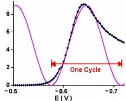
This number can be roughly translated into a scan rate by looking at Figure 1.
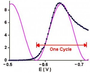
A linear scan for cadmium with a sine wave superimposed

[…]

There is a description of potentiostat stability (written by DK Roe) in the Kissinger & Heineman book (

How Fast Can My Potentiostat Scan?

Several times I have been asked a question about whether potentiostat Model XYZZY can scan at xyz V/s. Rarely is the answer in the data sheet for the instrument. Often, however, enough information is given to assess the limits. The path I follow to arrive at an answer is outlined here. An important fact about Read more about How Fast Can My Potentiostat Scan?[…]

There is a description of potentiostat stability (written by DK Roe) in the Kissinger & Heineman book (

Potentiostat Stability

Contact Dr Bobs Buzz - Electrochemical Methods

A while ago I received an email from an electrochemist who lamented:

“We have some problems with the 173, which we still prefer to use occasionally  because of its analog nature. … (The) potentiostat goes into oscillations.”

Although the M173 has a reputation for ‘stability’ it has always had problems with oscillation! These problems tend to be most troublesome when the more sensitive current ranges are used and when the cell capacitance is large. PAR had a ‘noise filter’ in their catalog for a long time that was really a ‘stability aid’ more than a ‘noise filter.’ It consisted of a capacitor that was placed between the counter electrode lead and the input jack of the M178 electrometer. This acts as a shunt for the higher frequency, oscillation-producing signals. A capacitor value of 0.01 µF is a good place to start. I think this stands the best chance of stabilizing your system.

[…]

This website uses cookies to ensure you get the best experience on our website. More information

The cookie settings on this website are set to "allow cookies" to give you the best browsing experience possible. If you continue to use this website without changing your cookie settings or you click "Accept" below then you are consenting to this. Please review our Privacy Policy

Close