

What Are They?
Why Are They Useful?
Introduction
Porous electrodes offer a high surface area to volume or weight ratio which is highly beneficial to a number of energy generation or storage devices. (e.g. Dye-Sensitized Solar Cells, Super-Capacitors, Fuel Cells, etc). Transmission lines are heavily used in modeling in Electrochemical Impedance Spectroscopy (EIS) experiments where porous systems are employed.
Though transmission lines are commonly used, an introductory paper was hard to find. This paper is intended to serve that purpose. It assumes basic knowledge of EIS and modeling using equivalent circuits as covered in our EIS application note.
Nomenclature and Notation
We will distinguish between the base electrode and the porous electrode and the various interfaces as shown in Figure 1.
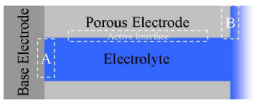
Figure 1. Porous Electrodes and the Nomenclature That Will Be Used in This Paper.
There are three regions that are of interest to the electrochemist. These are marked A, B, and Active Interface in Figure 1. A and B represent the interfaces between the base electrode and tip of the porous electrode with the electrolyte solution respectively. The active interface is the interface between the porous electrode and the electrolyte and this is the interface in question in most of the transmission line applications.
The base electrode and the porous electrode are electrically connected and generally based on the same material. For most systems, however, they behave sufficiently differently at the interface with the electrolyte that maintaining this distinction is useful.
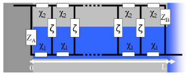
Figure 2. Transmission Line. X1, X2, ζ are the repeating circuit blocks on the rails and the steps. ZA and ZB correspond to impedances across the interfaces A and B defined in Figure 1.
A transmission line model in generic form is shown in Figure 2. ζ,X1,X2,,ZA and ZB are defined as subcomponents that can take various forms. These may be as basic as single resistors and as complicated as necessary. X1,X2, and ζ represent the solution impedance, bulk the impedance of the porous electrode material, and the impedance of the active interface respectively. We will refer to X1 and X2 as rail impedances and ζ as the step impedance using a ladder analogy. ZA and ZB are the impedances of the two interfaces A and B shown in Figure 1.
The parameter L represents the length of the transmission line (or the depth of the pore) as shown in Figure 2. It can be visualized as the number of steps in the ladder. Once the fitting is done, the numbers that are characteristic of the sample are X1L , X2Land ς/L . The value and the units of L has to be decided on before the fitting is attempted and has to be locked to a particular value. We will assume L to be unitless for this paper to keep this discussion straightforward In practice, knowledge of the thickness L allows to determine important parameters such as the conductivity and diffusion coefficient from the impedance fit results.
Read the complete Application Note Demystifying Transmission Lines >>
You will have an opportunity to download the complete article in PDF Format at Gamry.com