
Potentiostat Architectures – Passive I/E Converters
A Common Potentiostat Design
This style of I/E Converter is well suited to potentiostats with output currents of a few tenths of an ampere up to several  amperes. This scheme has been used by Gamry, PAR, Solartron, and perhaps others.
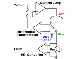
The I/E Converter is a “passive” design
The current path through the I/E converter only traverses passive components such as wires and resistors. No active components (such as op amps or transistors) are in the current path. The current measurement resistor is connected between the Working electrode and the potentiostat’s power supply ground (or “current return”).
The Working electrode is not at Virtual Ground
This is a consequence of the passive design. The working electrode voltage (vs the potentiostat’s internal ground) depends on the current flowing. In the sketch shown to the right, the working electrode will be at (i*Rm) volts. The actual voltage may be higher due to the resistance of the cell cable connecting the potentiostat to the working electrode!