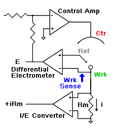
A Common Potentiostat Design
This style of I/E Converter is well suited to potentiostats with output currents of a few tenths of an ampere up to several  amperes. This scheme has been used by Gamry, PAR, Solartron, and perhaps others.
The I/E Converter is a “passive” design
The current path through the I/E converter only traverses passive components such as wires and resistors. No active components (such as op amps or transistors) are in the current path. The current measurement resistor is connected between the Working electrode and the potentiostat’s power supply ground (or “current return”).
The Working electrode is not at Virtual Ground
This is a consequence of the passive design. The working electrode voltage (vs the potentiostat’s internal ground) depends on the current flowing. In the sketch shown to the right, the working electrode will be at (i*Rm) volts. The actual voltage may be higher due to the resistance of the cell cable connecting the potentiostat to the working electrode!
Potentiostat with differential electrometer
A Potentiostat with a passive I/E Converter and Differential Electrometer.
The Electrometer is Differential
Because the working electrode is not at virtual ground a second input has been added to the electrometer. (See the blue arrow.) This input is called the Sense, Working Sense, or Reference 2 input by various manufacturers. The electrometer output reflects only the difference between its inputs. Both inputs must be high impedance inputs if small currents are to be measured.
Advantages
The I/E Converter amplifier must only report the iR drop across the current sense resistor. It is is not involved in the control of the working electrode and it does not have to be a high current amplifier. The frequency response of this style of I/E converter can be faster than the “active” design because of this. Its frequency response does not have to be sacrificed for potentiostat stability since the I/E converter is not involved in the “control loop.”
Because the electrometer is differential, a potentiostat of this design can be used to control the voltage across a membrane or across the interface between two immiscible liquids. In this application two reference electrodes are used. One is connected to the Reference input, and the other (on the other side of the membrane or interface) is connected to the Working Sense input.
Disadvantages
The Common Mode Rejection Ratio (CMRR) of the differential electrometer can have a profound influence on the stability of this potentiostat. There are two feedback paths through the differential electrometer. The path through the reference electrode is a net negative feedback path if you follow it from the reference electrode to the counter electrode via the electrometer and control amplifier. This path gives stability. The path through the Wrk Sense input, however, is a positive feedback path and is destabilizing.
The overall ‘gain’ of the control amplifier is higher with this scheme. This is another way of saying that the control amplifier must work harder to keep the working-reference voltage correct. Not only must it overcome the counter-reference resistance, but the voltage drop across the current measuring resistor as well. In many commercial designs, the voltage drop across this resistor is 100 mV or less, even at ‘full scale’ current. The differential amplifier often amplifies the voltage level (to a nominal 1V at full scale current) as well as buffering it.
