
Introduction
This Application Note presumes that you have a basic understanding of potentiostat operation. If you are not that knowledgeable concerning electrochemical instrumentation, please read Potentiostat Fundamentals before continuing. Experienced potentiostat users may skip the primer and read on.
It’s only natural that electrochemists concentrate on the working electrode. After all, reactions at the working electrode are  what they study. However, the reference electrode shouldn’t be ignored. Its characteristics can greatly influence electrochemical measurements. In some cases, an apparently “good” reference electrode can cause a complete failure of the system.
For reliable reference electrode performance, you should assign a “Lab Master” and treat it very, very carefully so it can serve as a standard for your other reference electrodes. Never use the Lab Master in an actual experiment. The only purpose of the Lab Master is to serve as a check for the other reference electrodes. If a reference electrode is suspected to be bad, you can check the potential versus the Lab Master. You can do that with a voltmeter, or with your Gamry Potentiostat by running and open circuit potential. If the potential difference is less than 2-3 mV, it’s OK. If it’s higher than 5 mV, it needs to be refreshed or discarded.
The Ideal Reference Electrode
Everyone agrees that an ideal reference electrode has a stable, well-defined electrochemical potential. Common reference electrodes (SCE, Ag/AgCl, Cu/CuSO4) meet this criterion when they are functioning properly. Many workers do not realize how often reference electrodes fail, causing drastic changes in their potential. Many complaints of potentiostat failures turn out to be reference electrode failures.
An ideal reference electrode should also have zero impedance. As discussed below, a reference electrode’s impedance can strongly affect the performance of a potentiostat.
Impedance of Laboratory Reference Electrodes
The impedance of a standard laboratory reference electrode is usually determined by the resistance of its isolation junction. This junction separates the reference electrode’s internal filling solution from the test electrolyte. A variety of junction types have been used, including ceramic frits, unfired Vycor™ frits, and asbestos threads. A slow flow of the filling solution through this junction is necessary for proper electrode operation. This flow can have the unwanted effect of altering the test solution composition, so the flow rate is kept to a minimum.
Unfortunately, slower flows require a more restricted flow path, and restrictions raise the resistance of electrolyte in the path. There is a fundamental tradeoff between electrode impedance and leakage rate. An SCE with a Vycor™ frit (for example Gamry Instruments’ P/N 930-03) will typically have an impedance of about 1 kohm. Ceramic junctions can have lower impedance than this while asbestos thread junctions have much higher impedance. We have prepared an application note that describes checking the impedance of your reference electrode.
Reference electrode junctions can become clogged, often without causing any significant shift in the reference’s DC potential. Adsorption of organic materials or precipitation of insoluble salts in the junction can both cause clogging. The resistance of a clogged junction can exceed 1 MΩ.
A double junction reference electrode is used to minimize filling solution contamination of the test electrolyte. A double junction is often required when chloride ion contamination is a concern. Reference electrodes are often filled with a saturated solution of very soluble KCl. Even the small amount of flow through the junction can produce a significant chloride concentration in the test solution. A double junction reference has two junctions. The first separates the reference electrode from an intermediate solution. This solution is then isolated from the test solution by a second junction. The intermediate solution is generally not as conductive as the KCl in the reference electrode junction, so the impedance of a double junction reference is usually more than twice that of a single junction electrode.
Electrochemists often use a Luggin Capillary to control the placement of the reference electrode relative to the working electrode. The Luggin capillary is filled with electrolyte and is used to position the sensing point of a reference electrode to a desired point in a cell. The Luggin capillary in a laboratory cell is made from glass or plastic. The Luggin holds the reference electrode as shown in Figure 1. The tip of the Luggin capillary near the working electrode is open to the test solution. The reference electrode senses the solution potential at this open tip.
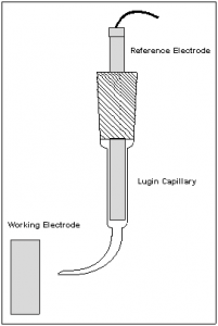
Figure 1. Luggin Capillary.
Note that the Luggin tip is significantly smaller than the reference electrode itself. The Luggin capillary allows sensing of the solution potential close to the working electrode without the adverse effects that occur when the large reference electrode is placed near the working electrode. The resistance of this electrolyte adds to the reference electrode impedance. Larger diameter, shorter Luggin capillaries have lower impedance than narrow bore, longer capillaries.
Corrosion chemists often use a pseudo-reference electrode in electrochemical corrosion testing. The pseudo-reference is a second piece of the working electrode material immersed in the same solution. If both the working electrode and pseudo-reference corrode similarly, they should have similar potentials. In most cases, the impedance of a pseudo-reference electrode is smaller than that of standard reference electrodes.
Bubbles and Reference Electrode Impedance
A reference electrode with a gas bubble interrupting its electrolyte path has a very high impedance. The bubble can be produced by electrolysis, from deaeration gas, outgassing of a heated electrolyte, or from trapped air. You should always check that your electrochemical setup has an unbroken electrolyte path from the working electrode to the sensing element within the reference electrode.
Be especially careful if you reference electrode has a flat isolation frit. If this flat surface is horizonal within the cell, it can easily trap a gas bubble. A 45 degree angle on this surface allows natural convection to remove any bubble that tries to stick on this surface.
Luggin capillaries are also notorious for problems with bubble entrapment.
Reference Electrode Impedance and DC Errors
High impedance reference electrodes can cause DC errors. At DC, the electrometer input current of most modern potentiostats is less than 50 pA. Ohm’s Law tells you that a reference electrode with a 20 kΩ resistance causes a DC voltage measurement error of less than one microvolt. Reference electrode potentials are typically only reproducible to about one millivolt, so a one microvolt error is inconsequential. Reference electrode impedance must get quite high before DC errors become significant.
Reference Electrode Impedance and AC Errors
The situation for AC signals is quite different. A typical reference input has a capacitance of 5 pF. A 20 kΩ reference electrode connected to this input forms an RC low pass filter, Figure 2, where low frequency signals input to the filter are transferred unchanged to the output. Higher frequencies are filtered out. This setup forms an RC low pass filter with a 100 nsec time constant. This filter will severely attenuate sine waves with frequencies greater than 1.5 MHz. It will also cause a phase shift of close to 4° at 100 kHz.
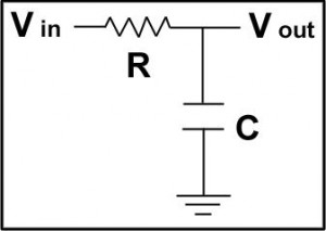
Figure 2. RC Low Pass Filter.
The effects become worse as the reference electrode impedance rises. Mansfeld, Lin, Chen, and Shih (1) have shown that EIS phase data can be severely distorted through this effect. They recommend use of a reference electrode combined with a capacitively coupled platinum wire to minimize these errors. See below for a further discussion of this combination.
Capacitive Cells and Potentiostat Stability
Read the complete Reference Electrodes application note. You will also have an opportunity to download this note in PDF format.