
Cyclic Voltammetry and Leakage Current
Purpose of This Note
This application note is the first part of an overview of electrochemical techniques used to test electrochemical capacitors (ECs). Electrochemical capacitors that are commercially available were tested to explain and discuss the theoretical background of cyclic voltammetry and leakage current measurement.
Introduction
This application note is part one of 3. Part 2 of this note discusses techniques that are also familiar to battery technologists. Part 3 describes theory and practice of EIS measurements on capacitors.
In contrast to batteries, ECs generally store energy by highly reversible separation of electrical charge while batteries use chemical reactions. ECs consist of two high-surface electrodes immersed in a conductive liquid or polymer called the electrolyte. The electrodes are separated by an ionic-conducting separator that prevents shorts between the two electrodes.
Compared to a battery, an electrochemical capacitor has the following advantages:
- Higher charge and discharge rates giving it a high power density
- Longer cyclelife (> 100,000 cycles)
- Low toxicity materials
- Operation over a wide temperature range
- Low cost per cycle
These are offset by some disadvantages:
- Higher self-discharge rate
- Lower energy density
- Lower cell voltage
- Poor voltage regulation
- High initial cost
Some applications use electrochemical capacitors in parallel with a battery. This combination provides better cycle life and higher power than a battery alone.
State of the art applications for electrochemical capacitors include:
- Hybrid Electric Vehicles (HEVs)
- Diesel engine starting systems
- Cordless power tools
- Emergency and safety systems
For more information read Brian Conway’s book on electrochemical capacitor technology:
Conway, B. E., Electrochemical Supercapacitors: Scientific Fundamentals and Technological Applications, Kluwer Academic Press / Plenum Publishers, New York, NY, 1999.
Similar Technology – Confusing Names
In technical papers and for commercial products a variety of terms are used to define types of capacitors. Unfortunately, arbitrariness leads to confusion and misleading designations.
These names are mostly product names and often used incorrectly. A selection is listed below:
- Supercapacitors
- Ultracapacitors
- Aerogel capacitors
This application note will conform to terminology shown in Figure 1.
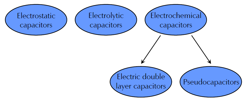
Figure 1 – Classification and designation of capacitors.
Figure 1 shows a schematic diagram of the classification of capacitors divided into three major groups:
Electrostatic capacitors use metal plates as electrodes that are separated by a dielectric with low conductivity, e.g. ceramics, glass, or even air.
Electrolytic capacitors use a metal foil as anode, e.g. aluminum or tantalum. During the anodizing process a metal oxide is formed which is used as dielectric. The cathode also consists of a metal foil.
Electrochemical capacitors use in contrast to electrostatic and electrolytic capacitors high-surface electrodes to increase capacitance. They can be divided in two subgroups depending on the storage mechanism.
- Electric double layer capacitors (EDLCs) use electrostatic charge separation to store energy. As the name says, a double layer is built up within the interface between electrolyte and electrode surface.
- Pseudocapacitors use beside electrostatic charge separation also highly reversible Faradaic surface reactions to store energy.
This application note uses only electrochemical capacitors for its measurements. Hence electrostatic and electrolytic capacitors will not be discussed.
Generally, EDLCs use activated carbon as electrode material. With surface areas of 1000 m2/g or more capacitances of 200 F/g can be reached. Pseudocapacitors use transition metal oxides (e.g. RuO2) or polymers as electrode materials.
To discuss several electrochemical techniques tests were performed on two different ECs in this note. Commercial 3 F EDLCs from Nesscap (P/N ESHSR0003C0002R7) and a 1 F PAS pseudocapacitor from Taiyo Yuden (P/N PAS0815LR2R3105) were used. The acronym PAS stands for Polyacenic Semiconductor which is a conductive polymer deposited on the electrodes.
The data in this note was recorded using Gamry’s PWR800 software. All plots were generated and evaluated using Gamry’s Echem Analyst.
Ideal Capacitor Characteristics
A capacitor is a storage device for electrical charge. A capacitor’s state-of-charge is easily measured. The stored charge of an ideal capacitor is proportional to the voltage, given by Equation 1:
(1)
Q is the capacitor’s charge in ampere-seconds (As) or coulombs (C), C is the capacitance in farads (F), and U is the voltage between the device’s terminals in volts (V).
The energy E stored in a capacitor can be calculated by Equation 2. The unit for the energy is joule (J):
(2)
An ideal capacitor with no current flow will store energy and charge for ever.
Power drawn from a capacitor during charge or discharge is proportional to the capacitor’s voltage and the electrical current, given by Equation 3:
(3)
P is the power in watts (W) and I is the electrical current in amperes (A). An ideal capacitor loses no power or energy during charge or discharge.
Capacitor Non-ideality
The ideal capacitor does not exist. In reality, capacitors have always had limitations and imperfections. The tests in this application note illustrates these limitations.
Voltage limitations
The description of ideal capacitors did not mention voltage limitations. Capacitors can only operate within a “voltage window” with both an upper and lower voltage limit. Voltages outside this window can cause electrolyte decomposition damaging the device.
The range of the voltage window strongly depends on the electrolyte which can be aqueous or nonaqueous. Generally, aqueous electrolytes are safer and easier to use. However, capacitors with nonaqueous electrolytes can have a wider voltage window.
Commercial single-cell ECs currently have an upper voltage limit below 3.5 V. For high-voltage applications multiple cells in series are used.
All commercial ECs are specified to be unipolar – the voltage on the plus (+) terminal must be more positive than the voltage on the minus (-) terminal. The lower voltage limit is usually zero volts.
ESR
Real capacitors suffer from power loss during charge and discharge. This loss is caused by resistances in electrical contacts, electrodes, and electrolyte. The sum of these resistances is called Equivalent Series Resistance (ESR). For ideal capacitors ESR is zero. It is specified on the data sheet for most commercial capacitors.
The power loss PLoss during charge or discharge is given by Equation 4:
(4)
This power is lost as heat – under extreme conditions enough heat to damage the device.
The ESR can be modeled as a resistor in series with an ideal capacitor.
Leakage current
Ideal capacitors maintain constant voltage without current flow from an external circuit. Real capacitors require a current, called leakage current, Ileakage, to maintain constant voltage.
Leakage current will slowly discharge a charged capacitor that has no external connections to its terminals. This process is called self discharge.
Ileakage can be calculated using Equation 5, multiplying the capacitance by the rate of voltage change:

(5)
Leakage current can be modeled as a resistor that is parallel with a capacitor. This model is a simplification of the voltage and time dependence of leakage current.
As an example, a leakage current of 1 µA on a 1 F capacitor held at 2.5 V implies a 2.5 MΩ leakage resistance. The time constant for the self-discharge process would be 2.5×10⁶ seconds – nearly a month.
Time effects
The time constant τ for a charge or discharge process of an ideal capacitor in series with an ESR can be calculated by Equation 6:
(6)
Typically, τ is between 0.1 and 20 seconds. A voltage step into a capacitor with ESR should create a current that exponentially decays towards zero. In a device with leakage current, the post-step current decay stops at the leakage current.
Time effects can be caused by slow Faradaic reactions occurring at imperfections on the surface of the electrode material. Carbon surfaces used for most electrochemical capacitors have oxygen containing groups (hydroxyl, carbonyl…) that are plausible reaction sites.
Commercial ECs do not show this simple behavior. As seen further below, commercial capacitors held at a constant potential take days to reach their specified leakage current. The time needed is much greater than predicted by τ.
Dielectric absorption is a phenomenon that can also occur on capacitors. It is a short-term time effect and is caused by non-electrostatic charge storage mechanisms with very long time constants.
Time effects also can be a side effect of porosity inherent in high-capacity electrodes. The deeper a pore, the higher the electrolyte resistance. Hence different areas of the electrode surface see different resistances.
As discussed more precisely in part 3 of this note, this complicates the simple capacitor model into a distributed element that is also called transmission line model.
Cycle life
An ideal capacitor can be charged and discharged for an infinite number of cycles. Many commercially available ECs approach this ideal – they are specified for 105 or even 106 charge/discharge cycles. In contrast, secondary batteries’ cycle-life specifications are typically hundreds of cycles.
The cycle life for all rechargeable devices depends on the exact conditions under which cycling occurs. Applied current, voltage limits, device history, and temperature are all important. Part 2 will go more into detail.
Cyclic Voltammetry
Read the complete application note. You will also have an opportunity to download this note in PDF format.