What is a Constant Phase Element?
The Constant Phase Element (CPE) is a non-intuitive circuit element that was discovered (or invented) while looking at the response of real-world systems. In some systems the Nyquist plot (also called the Cole-Cole plot or Complex Impedance Plane plot) was expected to be a semicircle with the center on the x-axis. However, the observed plot was indeed the arc of a circle, but with the center some distance below the x-axis.
These depressed semicircles have been explained by a number of phenomena, depending on the nature of the system being investigated. However, the common thread among these explanations is that some property of the system is not homogeneous or that there is some distribution (dispersion) of the value of some physical property of the system.
CPE equations
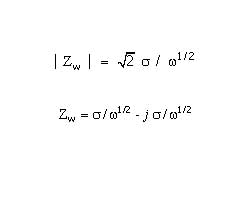
Mathematically, a CPE’s impedance is given by
1 / Z = Y = Q° ( j omega )n
where Q° has the numerical value of the admittance (1/ |Z|) at omega =1 rad/s. The units of Q° are S•sn (ref 1).
A consequence of this simple equation is that the phase angle of the CPE impedance is independent of the frequency and has a value of -(90*n) degrees. This gives the CPE its name.
When n=1, this is the same equation as that for the impedance of a capacitor, where Q° =C.
1 / Z = Y = j omega Q° = j omega C
When n is close to 1.0, the CPE resembles a capacitor, but the phase angle is not 90°. It is constant and somewhat less than 90° at all frequencies. In some cases, the ‘true’ capacitance can be calculated from Q° and n
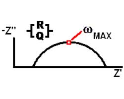
The Nyquist (Complex Impedance Plane) Plot of a CPE is a simple one. For a solitary CPE (symbolized here by Q), it is just a straight line which makes an angle of (n*90°) with the x-axis as shown in pink in the Figure. The plot for a resistor (symbolized by R) in parallel with a CPE is shown in green. In this case the center of the semicircle is depressed by an angle of (1-n)*90°
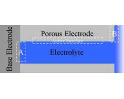
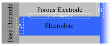
What Causes a CPE?
[…]


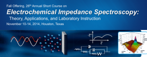 Course Overview


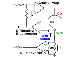
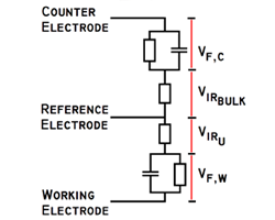
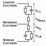
 amperes. This scheme has been used by Gamry, PAR, Solartron, and perhaps others.