Even if the I/E circuit is not overloaded, it can have severe influence on potentiostat stability.

Potentiostat Architectures – Active I/E Converters

The Classical Potentiostat The schematic at the right is the classical potentiostat design shown in nearly every modern electrochemistry textbook. It has three basic features. The Working electrode is at Virtual Ground. The working electrode is at the same potential as the potentiostat’s electronic ground. This ground is often connected to Earth Ground. The electrometer Read more about Potentiostat Architectures – Active I/E Converters[…]

References on Corrosion Theory and Electrochemical Corrosion Tests

Many of the following ‘references’ are available at Amazon.com and can be viewed at our Bookstore. DC Electrochemical Test Methods, N.G. Thompson and J.H. Payer, National Association of Corrosion Engineers, 1440 South Creek Drive, Houston, TX 77084-4906. Phone: 281-228-6200. Fax: 281-228-6300. ISBN: 1-877914-63-0. Recommended! Principles and Prevention of Corrosion, Denny A. Jones, Prentice-Hall, Upper Saddle Read more about References on Corrosion Theory and Electrochemical Corrosion Tests[…]

Electrochemical Quantitative Corrosion Theory

Quantitative Corrosion Theory

In the previous post (Electrochemical Corrosion Measurements Primer) we pointed out that Icorr cannot be measured directly. In many cases, you can estimate it from current versus voltage data. You can measure a log current versus potential curve over a range of about one half volt. The voltage scan is centered on Eoc. You then fit the measured data to a theoretical model of the corrosion process.

The model we will use for the corrosion process assumes that the rates of both the anodic and cathodic processes are controlled by the kinetics of the electron transfer reaction at the metal surface. This is generally the case for corrosion reactions. An electrochemical reaction under kinetic control obeys Equation 1-1, the Tafel Equation.

the Tafel Equation

Equation 1-1

[…]

Electrochemical Corrosion Measurements

Electrochemical Corrosion Measurements Primer

Most metal corrosion occurs via electrochemical reactions at the interface between the metal and an electrolyte solution. A thin film of moisture on a metal surface forms the electrolyte for atmospheric corrosion. Wet concrete is the electrolyte for reinforcing rod corrosion in bridges. Although most corrosion takes place in water, corrosion in non-aqueous systems is not unknown.

Corrosion normally occurs at a rate determined by an equilibrium between opposing electrochemical reactions. The first is the anodic reaction, in which a metal is oxidized, releasing electrons into the metal. The other is the cathodic reaction, in which a solution species (often O2 or H+) is reduced, removing electrons from the metal. When these two reactions are in equilibrium, the flow of electrons from each reaction is balanced, and no net electron flow (electrical current) occurs. The two reactions can take place on one metal or on two dissimilar metals (or metal sites) that are electrically connected.

Basics of electrochemical corrosion measurement

Figure 1-1. Corrosion Process Showing Anodic and Cathodic Current Components.

Figure 1-1 diagrams this process. The vertical axis is potential and the horizontal axis is the logarithm of absolute current. The theoretical current for the anodic and cathodic reactions are shown as straight lines. The curved line is the total current — the sum of the anodic and cathodic currents. This is the current that you measure when you sweep the potential of the metal with your potentiostat. The sharp point in the curve is actually the point where the current changes signs as the reaction changes from anodic to cathodic, or vice versa. The sharp point is due to the use of a logarithmic axis. The use of a log axis is necessary because of the wide range of current values that must be displayed during a corrosion experiment. Because of the phenomenon of passivity, it is not uncommon for the current to change by six orders of magnitude during a corrosion experiment.

[…]

Electrochemical Quartz Crystal Microbalance - Gamry Instruments's eQcm

Quartz Crystal Microbalance

The Quartz Crystal Microbalance (QCM) is an exciting tool for the electrochemist. With it, the researcher can now follow not only the current that flows, but the weight changes of the electrode, too! This is a valuable tool when studying reactions which involve films, adsorbates, metal deposition, corrosion, or monolayer formation. It is sensitive enough Read more about Quartz Crystal Microbalance[…]

cyclic voltammetry scan rate

How Fast a CV Can I Measure Reliably ?

Being able to scan rapidly does not insure that the results will be meaningful! The speed of the current measurement circuitry is often the limiting factor!

The key to finding the practical limit for obtaining meaningful fast scan cyclic voltammograms is nearly always finding the speed of the current measurement. Here the researcher has an important role to play: It is the researcher who must select the current range to use for fast cyclic voltammetry. The autoranging capability of many modern computer controlled potentiostats generally cannot be used because the decisions cannot be made and implemented fast enough.

Because of stray (and deliberately added) capacitances, the current measuring circuitry generally becomes slower as the full scale current decreases. Obtaining the fastest scan requires a tradeoff of scan rate, electrode size, analyte concentration, current range, and acceptable noise in the measurement. It is often better to use a less sensitive current scale (larger full scale current) coupled with a larger pre-amplification factor on the ADC, data recorder, or oscilloscope used. Although this approach is likely to increase the noise in the measurement, it does allow a higher scan rate to be realized.

The speed or frequency response of each current range can sometimes be found in the manufacturer’s data sheet under “Current Measurement” or sometimes as a “System Specification” if a specific current range is quoted along with the bandwidth.

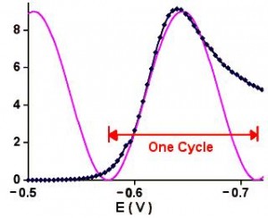
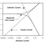
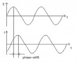
This number can be roughly translated into a scan rate by looking at Figure 1.

A linear scan for cadmium with a sine wave superimposed

[…]

There is a description of potentiostat stability (written by DK Roe) in the Kissinger & Heineman book (

How Fast Can My Potentiostat Scan?

Several times I have been asked a question about whether potentiostat Model XYZZY can scan at xyz V/s. Rarely is the answer in the data sheet for the instrument. Often, however, enough information is given to assess the limits. The path I follow to arrive at an answer is outlined here. An important fact about Read more about How Fast Can My Potentiostat Scan?[…]

There is a description of potentiostat stability (written by DK Roe) in the Kissinger & Heineman book (

Fitting EIS Data – Adding Components

Dr. Bob on  EISOne guideline that I have heard recommended (although I cannot give a reference for it) is that data over a decade range of frequency is required to support each circuit component.

All curve-fitting software should report some measure of the “goodness of fit.” Often this is the chi-squared parameter ( X2 ) or a value related to it. Boukamp makes the recommendation that the value of X2 should decrease by tenfold if a new circuit element is introduced into the circuit model. The tenfold decrease provides the justification for including the new circuit element. If the inclusion of an additional circuit element does not substantially improve the goodness-of-fit (as evidenced by the decrease in the X2 value), then based on Occam’s Razor, you should keep the simpler model, or continue your search for an improved one.

The old joke about the ability to “fit an elephant” if you use enough parameters is all too true with impedance data. Each component added to the model should have a physical explanation. Adding components only because they make the fit look better (smaller X2) without a physical interpretation is the equivalent to “fitting an elephant.”

What is X2?

[…]

Development of a Cyclic Voltammetry Method

For DNA Electrochemical Detection on Microfluidic Gene Chip On the microfluidic gene chip, due to high difficulty in temperature changes frequently and products detecting equipment miniaturize, the conventional methods of DNA detection can’t meet the requirements. In this paper, a newly electrochemical method, cyclic voltammetry, basing on a set of special electrodes and the Loop-mediated Read more about Development of a Cyclic Voltammetry Method[…]

National Science Foundation

NSF Creates Electrochemical Research Center

NSF Creates industry electrochemical research center at Ohio University

The Center for Electrochemical Engineering at Ohio Univ.’s Russ College of Engineering and Technology has received a National Science Foundation (NSF) award to establish a new industry university cooperative research center in Athens, Ohio, with partner site Washington University-St. Louis.

Led by Russ Professor of Chemical Engineering and Center for Electrochemical Engineering Director Gerri Botte, research at the new Center for Electrochemical Processes and Technology (CEProTECH) will focus on electrochemical alternatives to conventional chemical and biological processes, with the goal of enhancing advanced production capabilities, via a consortium model.

Consortium members will have access to pre-competitive, industry-driven research results and a dedicated 20,000-square-foot facility, located on Mill Street in Athens, Ohio, with more than $7 million in state-of-the-art equipment and infrastructure; students with specialized expertise in electrochemical engineering; and relationships with faculty, government labs and agencies, and other industry members.

[…]

Electrochemistry Impedance Spectroscopy Basics

Basics of Electrochemical Impedance Spectroscopy

This application note presents an introduction to Electrochemical Impedance Spectroscopy (EIS) theory and has been kept as free from mathematics and electrical theory as possible. If you still find the material presented here difficult to understand, don’t stop reading. You will get useful information from this application note, even if you don’t follow all of the discussions.

Four major topics are covered in this Application Note.

  • AC Circuit Theory and Representation of Complex Impedance Values
  • Physical Electrochemistry and Circuit Elements
  • Common Equivalent Circuit Models
  • Extracting Model Parameters from Impedance Data

No prior knowledge of electrical circuit theory or electrochemistry is assumed. Each topic starts out at a quite elementary level, then proceeds to cover more advanced material.

AC Circuit Theory and Representation of Complex Impedance Values

Impedance Definition: Concept of Complex Impedance

concept of electrical resistance

(1)

Almost everyone knows about the concept of electrical resistance. It is the ability of a circuit element to resist the flow of electrical current. Ohm’s law (Equation 1) defines resistance in terms of the ratio between voltage, E, and current, I.

While this is a well known relationship, its use is limited to only one circuit element — the ideal resistor. An ideal resistor has several simplifying properties:

  • It follows Ohm’s Law at all current and voltage levels.
  • Its resistance value is independent of frequency. AC current and voltage signals though a resistor are in phase with each other.

[…]

Reference Electrodes

Introduction

This Application Note presumes that you have a basic understanding of potentiostat operation. If you are not that knowledgeable concerning electrochemical instrumentation, please read Potentiostat Fundamentals before continuing. Experienced potentiostat users may skip the primer and read on.

It’s only natural that electrochemists concentrate on the working electrode. After all, reactions at the working electrode are Silver Chloride Reference Electrode
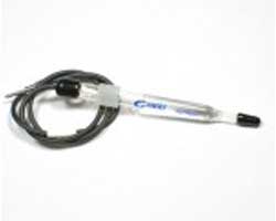
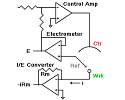
what they study. However, the reference electrode shouldn’t be ignored. Its characteristics can greatly influence electrochemical measurements. In some cases, an apparently “good” reference electrode can cause a complete failure of the system.

For reliable reference electrode performance, you should assign a “Lab Master” and treat it very, very carefully so it can serve as a standard for your other reference electrodes. Never use the Lab Master in an actual experiment. The only purpose of the Lab Master is to serve as a check for the other reference electrodes. If a reference electrode is suspected to be bad, you can check the potential versus the Lab Master. You can do that with a voltmeter, or with your Gamry Potentiostat by running and open circuit potential. If the potential difference is less than 2-3 mV, it’s OK. If it’s higher than 5 mV, it needs to be refreshed or discarded.

[…]

This website uses cookies to ensure you get the best experience on our website. More information

The cookie settings on this website are set to "allow cookies" to give you the best browsing experience possible. If you continue to use this website without changing your cookie settings or you click "Accept" below then you are consenting to this. Please review our Privacy Policy

Close